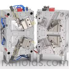
Automotive components often combine complex geometry with strict functional and appearance requirements, making tooling development an important part of the manufacturing process. A well-engineered Auto Parts Mould must account for material behavior, component structure, cooling, ejection, surface finish, and production conditions from the beginning of the design process. These factors work together to influence both tooling reliability and the quality of finished parts.
The design of an automotive component usually begins with an assessment of its intended function and assembly environment. Plastic parts may need to connect with other components, accommodate fasteners, support clips, protect internal systems, or provide a finished visual surface. This means mold designers must understand more than the external shape of the component. Wall thickness, ribs, bosses, mounting points, draft angles, and parting lines can all affect how the mold should be constructed.
Material behavior is equally important. Automotive plastics can differ significantly in shrinkage, flow characteristics, thermal behavior, impact resistance, and dimensional stability. When a material is selected, its behavior should be considered together with cavity geometry and processing requirements. A mold designed without sufficient attention to material characteristics may experience filling challenges, uneven shrinkage, deformation, or other production issues.
Flow analysis can provide useful information during the development stage. By simulating polymer movement through the cavity, engineers can evaluate possible filling patterns and identify areas where adjustments may be necessary. Gate positioning, runner configuration, venting, and cavity balance can then be reviewed before the physical mold is manufactured. This approach can reduce development risks and make later mold trials more productive.
Venting is a particularly important part of cavity design. During injection, displaced air must leave the cavity effectively. Insufficient venting can contribute to trapped air, burn marks, incomplete filling, or appearance defects. Proper vent locations and dimensions should be determined according to the component geometry and expected material flow. Venting should also be designed so that it does not interfere with important cosmetic or functional surfaces.
Cooling system design has a major influence on cycle stability and dimensional consistency. A component with uneven wall thickness or deep structural features may not cool uniformly if the mold lacks an appropriate thermal management strategy. Engineers therefore need to consider cooling channel placement, cavity geometry, material characteristics, and areas that may retain heat. Better thermal balance can help reduce deformation and improve repeatability between production cycles.
Precision machining is another fundamental stage of mold manufacturing. CNC equipment is commonly used to create complex cavity and core structures, while EDM can support the production of narrow slots, sharp details, and other difficult geometries. Depending on the required surface condition, additional grinding and polishing operations may be performed. The transition between these processes needs to be carefully controlled because small deviations can influence part fit and appearance.
Surface finishing deserves particular attention when molds are used for visible automotive components. The cavity surface may require a polished finish, controlled texture, or carefully defined transition areas. The desired result should be considered during initial tooling design because surface treatment can interact with geometry, material behavior, and demolding conditions. Consistent finishing also helps reduce differences between cavity regions.
Ejection is another area where engineering decisions can affect the finished component. Automotive parts may contain delicate edges, curved surfaces, deep cavities, or cosmetic areas that cannot tolerate visible ejector marks. Ejector pins, sleeves, lifters, and other mechanisms should therefore be positioned according to the structural characteristics of the component. Adequate draft and balanced ejection forces can support smooth release while reducing unnecessary stress.
Tool assembly and trial molding provide opportunities to verify the complete system. During trials, engineers can examine filling behavior, part dimensions, surface appearance, ejection performance, and assembly compatibility. If an issue is identified, the root cause should be evaluated rather than relying only on local adjustments. This systematic approach helps ensure that tooling modifications address the actual manufacturing problem.
Quality management should continue throughout the mold lifecycle. Inspection of machined components, cavity dimensions, mold alignment, cooling passages, and moving mechanisms can help identify potential issues before production. Maintenance planning is also important because repeated molding cycles can gradually affect moving parts, sealing surfaces, and other areas exposed to mechanical or thermal stress.
Digital design and manufacturing technologies further connect these stages. CAD data can support design communication, CAE can provide simulation-based evaluation, and CAM systems can translate approved geometry into machining operations. When these technologies are integrated with experienced engineering judgment, tooling development becomes more structured and traceable.
For manufacturers developing complex vehicle components, Taizhou Renxin Mould Co., Ltd. applies engineering, simulation, precision manufacturing, and finishing processes to automotive tooling projects, with more information about its capabilities available at https://www.rxmolds.com when evaluating an Auto Parts Mould for professional production applications.