A Procedure Governed by Precision and Safety
The process of high voltage capacitor installation is a critical path activity in substation and industrial power system upgrades, demanding a meticulous balance of electrical engineering precision and uncompromising safety protocols. Unlike passive equipment, these units store substantial amounts of energy, making their integration into an energized system a task with zero tolerance for error. A successful project moves beyond simply mounting and wiring hardware; it involves rigorous planning, adherence to standards, and a sequence of verification steps to ensure the bank enhances grid stability without introducing new risks.
Pre-Installation Planning and Site Preparation
Long before the first unit is unloaded, comprehensive planning sets the stage. This includes a detailed review of system studies to confirm the bank’s size, location, and switching scheme are optimal. The physical site is prepared: a reinforced concrete pad is poured to specification, grounding grid connections are made accessible, and clearances from other equipment (as per the National Electrical Safety Code or IEC standards) are verified. All personnel involved undergo a job-specific safety briefing covering hazards like stored energy, arc flash potential, and working heights. The required PPE—including voltage-rated gloves, arc-flash suits, and face shields—and specialized tools, such as calibrated torque wrenches for bus connections and insulated lift devices, are assembled and inspected.
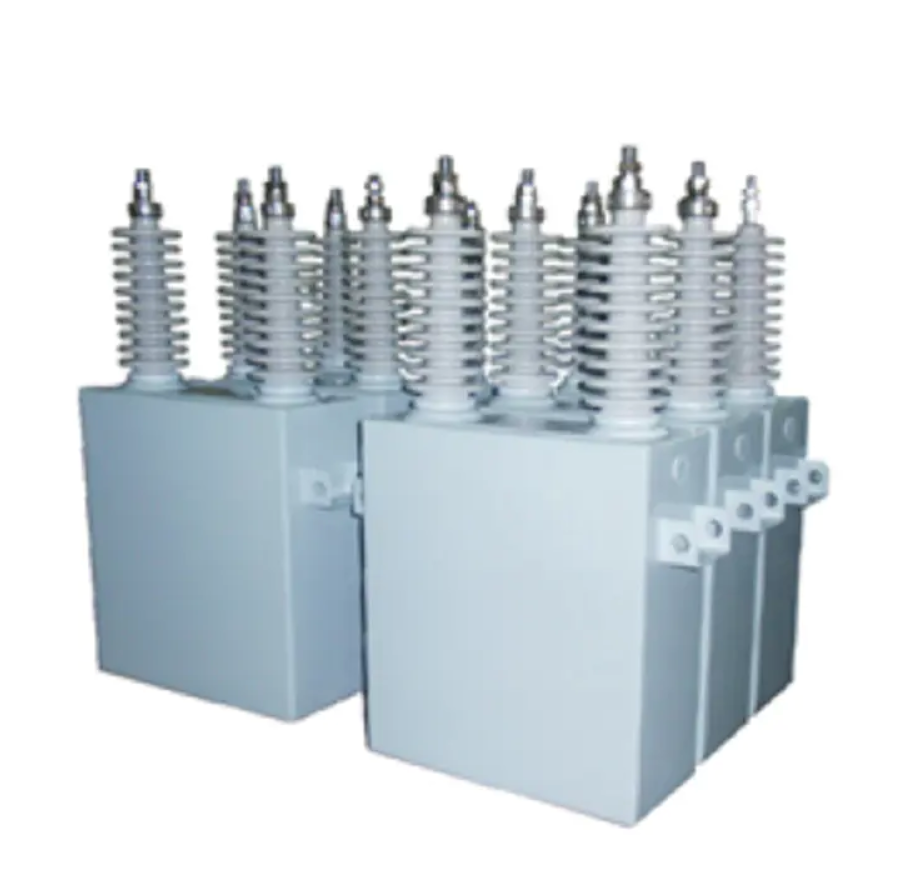
Mechanical Mounting and Electrical Bonding
The physical installation begins with positioning the capacitor units or the pre-assembled rack on the foundation. Units must be leveled and anchored according to the manufacturer’s specifications to withstand mechanical stress and wind loading. The next crucial phase is establishing a robust, low-impedance grounding connection. The steel frame or enclosure of each unit is bonded to the site’s main grounding grid using specified conductors and lugs. This path is essential for safety, providing a controlled route for fault currents and ensuring the enclosure remains at earth potential. Following this, the inter-unit buswork or cables are installed. Each connection point must be cleaned, treated with antioxidant compound if required, and torqued to the exact value specified by the manufacturer to ensure a cold, low-resistance joint that will not overheat under load.
Pre-Energization Testing and Verification
With the bank physically installed but isolated, a series of critical checks is performed. First, technicians use a megohmmeter (megger) to verify the insulation integrity of each unit and the overall bank, ensuring there are no ground faults from shipping damage. Second, and most importantly, the internal discharge devices are verified to be functional, typically by measuring the time it takes for the residual voltage to decay after a DC test charge. Phasing and polarity are double-checked against the system’s single-line diagram; a wiring error here can lead to a catastrophic phase-to-phase short upon energization. All control and protection wiring from the bank to the switching device and relay panel is continuity-tested. Only after all these tests are signed off is the installation considered ready for the live connection.