
In the hierarchical structure of a well's architecture, the casing system and the hydraulic pumping units represent the skeletal protection and the circulatory heart of the operation, respectively. For engineers specialising in geological exploration and deep-well construction, a rigorous understanding of the mechanical properties and fluid dynamics of these components is essential for maintaining borehole stability and ensuring efficient energy transmission to the bit. [1]
1. Casing Systems: Structural Integrity and Borehole Isolation
The casing serves as a permanent structural liner for the borehole, consisting of high-strength steel tubes that are inserted into the well and cemented in place to seal the annular space between the pipe and the formation. From an engineering perspective, the casing design is a critical component of the overall well plan, dictated by the "telescoping" geometry of the well—where diameters decrease progressively with depth to manage geological risks such as collapses and high-pressure kicks.
1.1 Engineering Selection and Material Grades
The selection of casing grades and weights is an optimization problem involving variables such as local lithology, formation pore and fracture pressures, geothermal gradients, and logistical constraints. Engineers typically refer to the American Petroleum Institute (API) Bulletin 5C2 for performance properties. Casing must be engineered to withstand:
-
Axial Tension: Supporting its own weight during installation.
-
External Collapse Pressure: Resisting the hydrostatic pressure of the mud and formation fluids.
-
Internal Burst Pressure: Containing high-pressure wellbore fluids during a kick or production.
-
Mechanical Wear: Withstanding the friction of rotating tool joints during subsequent drilling phases.
1.2 Functional Motivations for Casing Installation
The deployment of casing is driven by several operational imperatives, as summarized in the engineering literature:
-
Pressure Containment: Isolating high-pressure zones and preventing fluid migration between permeable formations.
-
Mechanical Support: Providing a stable platform for the wellhead and Blowout Preventer (BOP) stack.
-
Structural Stability: Preventing the sloughing or collapse of unconsolidated surface formations.
-
Hydraulic Conduit: Providing a stable return path for drilling mud to the surface during circulation.
1.3 The Casing Sequence and Profile
A standard casing program follows a specific technical sequence based on the "casing points"—depths where significant changes in formation properties occur.
1. Conductor/Drive Casing: Protects unconsolidated surface layers from erosion by drilling fluids.
2. Surface Casing: Prevents the contamination of freshwater sands and serves as the first anchor point for the BOP stack.
3. Intermediate Casing: Often set in transition zones above significant overpressures to isolate "trouble zones" like lost-circulation areas.
4. Production Casing: The final string through which the well is completed and produced.
5. Liners: A specialized string that does not extend to the surface but is hung from the previous casing shoe to provide a sealed environment for deep-well completion while reducing steel costs.
Failure to correctly identify the "casing seat" (shoe) can lead to wellbore instability or the failure to reach the target depth.
2. Mud Pumps: The Hydraulic Power Plant
If the drill string provides the mechanical torque, the pumps provide the hydraulic energy necessary to circulate mud, clean the bit, and power downhole motors. For a drilling rig, at least three pumps are typically maintained for safety and redundancy.
2.1 Mechanical Design: Duplex vs. Triplex Systems
Modern drilling operations utilize two primary types of reciprocating positive-displacement pumps:
-
Double-Action (Duplex) Pumps: These utilize two cylinders where fluid is moved on both the forward and backward strokes of the piston.
-
Single-Action (Triplex) Pumps: These utilize three cylinders, moving fluid only on the forward stroke. Triplex pumps are currently the industry standard due to their ability to handle higher pressures and provide smoother flow rates.
2.2 Mathematical Modeling of Pump Performance

For Double-acting duplex pumps, the theoretical flow is modeled as:
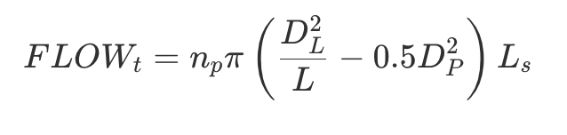
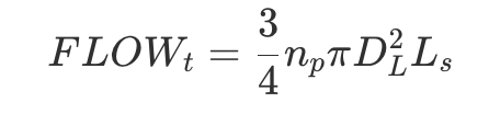
For Single-acting triplex pumps, the calculation is:
To determine the actual power output, engineers must apply a volumetric efficiency factor ![]() which is typically
which is typically ![]() for high-performance systems.
for high-performance systems.
2.3 Hydraulic Power and System Dampening
The theoretical hydraulic power ![]() is the product of discharge pressure
is the product of discharge pressure ![]() and flow rate:
and flow rate:
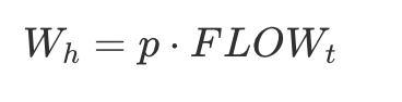
Engineers must calculate this power to compensate for pressure losses throughout the borehole and mud circuit. Typical working pressures range from 5,000 psi (34.5 MPa) to 7,500 psi (51.7 MPa). While dampeners are installed to smooth the pump's action, the acoustic noise pulsation related to the stroke frequency is a known modulation factor in Seismic While Drilling (SWD) data, requiring careful filtering during signal processing.
3. Operational Integration: Casing, Pumps, and Efficiency
The synergy between the casing and the pump system is evident in the mud circulation cycle. The pumps force mud into the drill pipes, through the bit nozzles, and back up the annulus between the drill string and the casing. In Geological Exploration, the mud serves a dual role: cooling the bit and transporting cuttings back to the surface for analysis.
The casing design significantly impacts the hydraulic efficiency; a narrow annulus between the casing and the drill pipe increases the annular velocity ($V_a$), which is the ratio of flow rate to the cross-sectional area:
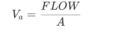
Correct ![]() management is vital to ensure that cuttings do not accumulate at the bottom of the well, especially in deviated or horizontal wells where the risk of stuck pipe is elevated.
management is vital to ensure that cuttings do not accumulate at the bottom of the well, especially in deviated or horizontal wells where the risk of stuck pipe is elevated.
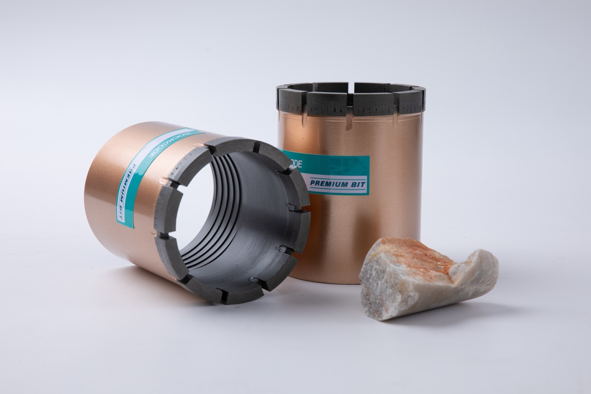
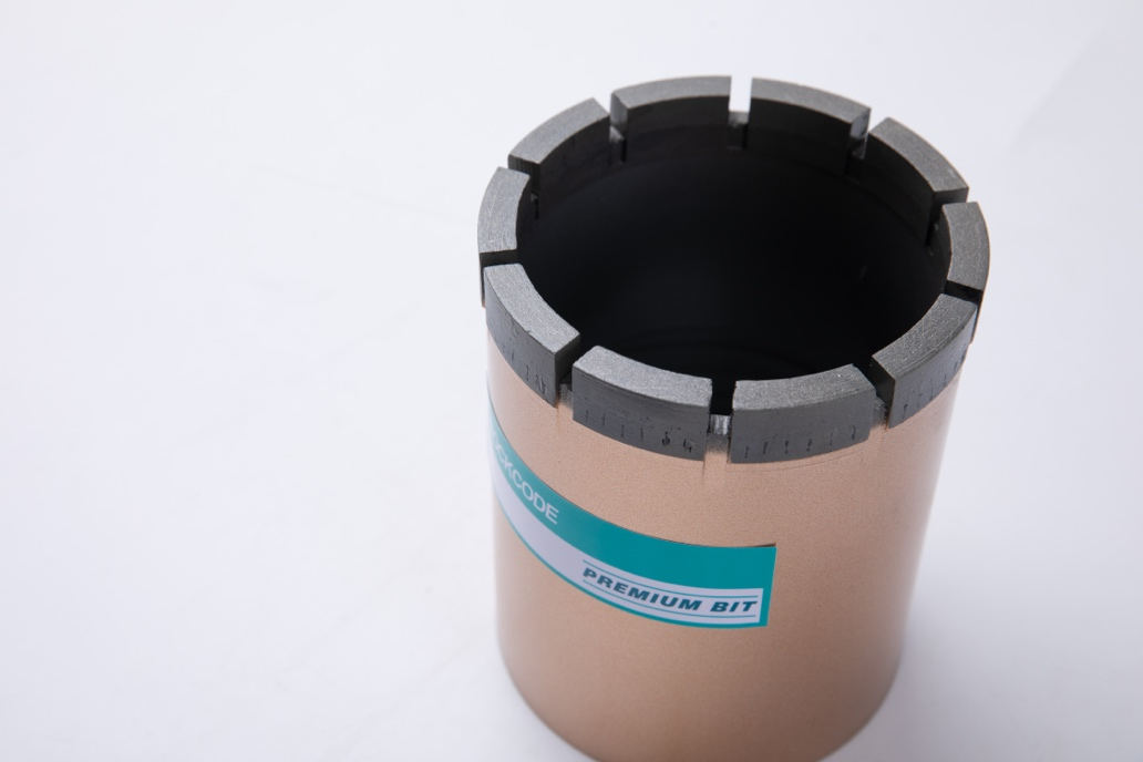
→ For more information about ROCKCODE’s Products, please visit: https://www.rockcodebit.com/casing-rod-shoe
→ Email us at: info@rockcodebit.com
→ Information in this article is for general reference only. For specific drilling projects and drilling bits, please consult qualified professionals. Thank you.
Source
【1】Poletto, F., & Miranda, F. (2022). Seismic while drilling : fundamentals of drill-bit seismic for exploration (2nd edition.).
https://www.rockcodebit.com/casing-systems-and-hydraulic-pumping-units-in-drilling-engineering.html